This is an installation in 2020 of a Waterfurnace NSW040 ground-loop heatpump in a 2600 sq ft house, using water-filled underfloor heating pipes set in concrete - a concrete slab over styrofoam insulation on the lower floor, and a 1.5 inch screen over plywood on upper floors. The flooring is mostly hardwood, with some tile, laid directly on the concrete.
The ceilings have foamed-in-place insulation with an RSI value of 5.1. The lower walls are ICF concrete with RSI 3.9, the upper walls 6" wooden studs with fibreglass batts with RSI 2.4. There is about 540 sq ft of windows with SI U-value 1.6. My estimate of the heating load for a -7C day is about 5.9kW, not including any solar gain.
The heatpump is rated 39100Btu/hr (11.45kW) with a ground temperature of +10C, giving a COP of 3.9 (equivalent to a 390% thermal efficiency compared to resistive electric heat or gas boiler).
There are two vertical boreholes some 4" diameter extending some 200 feet into the water table, about the same as the drinking water well, back-filled with bentonite clay for good thermal conductivity
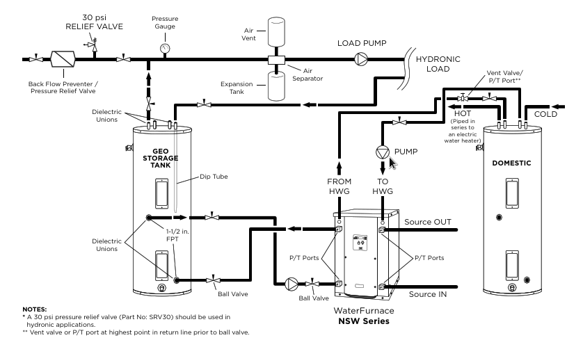
Taken from the Waterfurnace installation manual.
Photos
Click for larger version
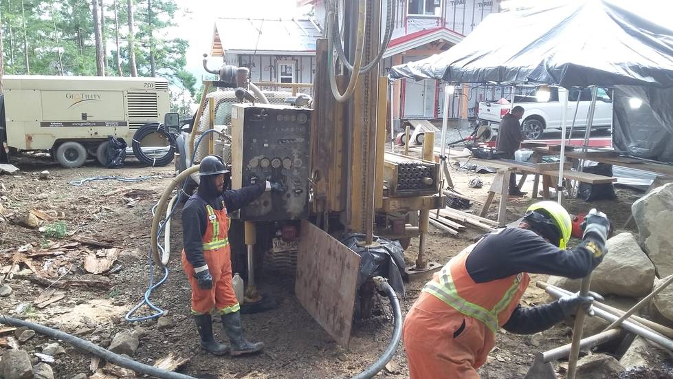 Drilling one of two boreholes for the ground loop
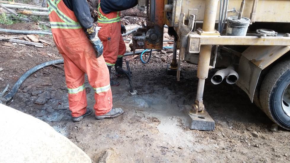 Preparing the casing
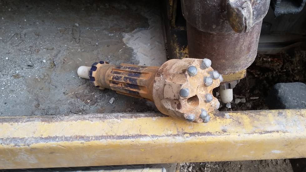 Rock drill
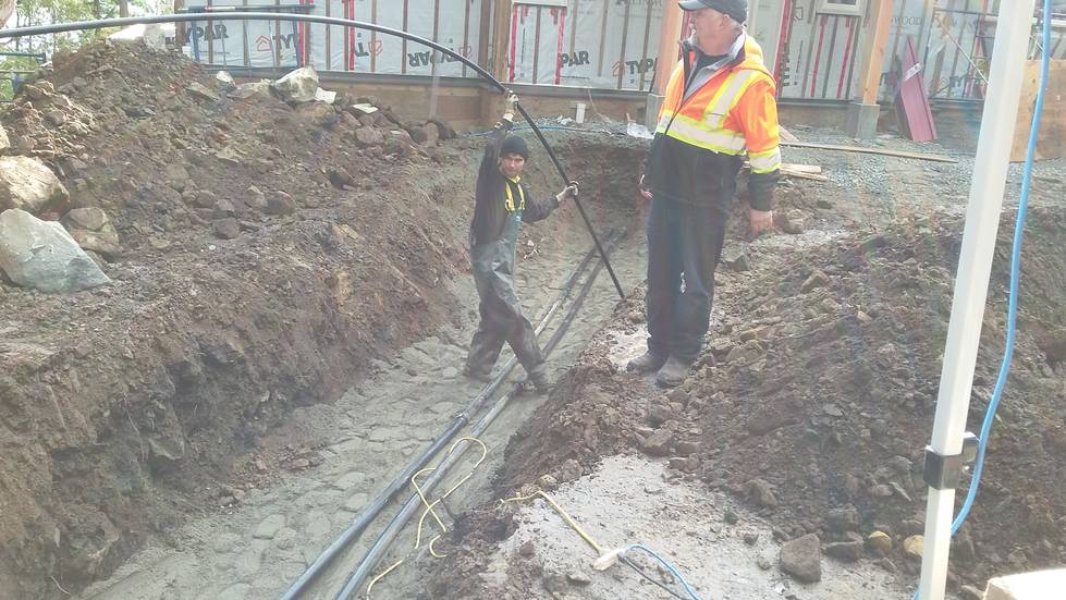 Laying horizontal pipe
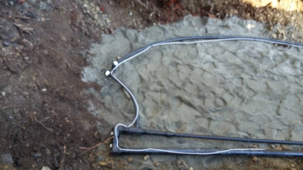 Connections to vertical boreholes, with sensor tape
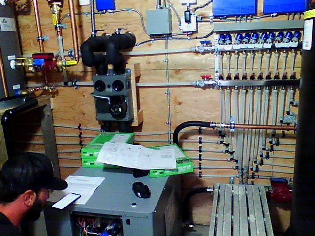
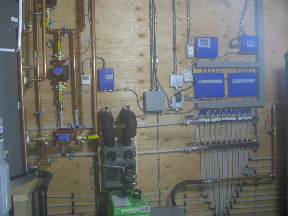
Technician commissioning the heatpump.
On the wall behind is the pump for the ground loop, with
insulated pipes leading through the wall to the horizontal trench.
On the far right is the buffer tank, containing hot water
created by the heat pump, whith a circulating pump (in red).
On the top left is a preheat tank for domestic hot water, heated by a heat
exchanger from the hot side loop. Out of sight to the left is
a conventional hot water tank with electric immersion heaters, taking
the water to the full required temperature for a hot shower.
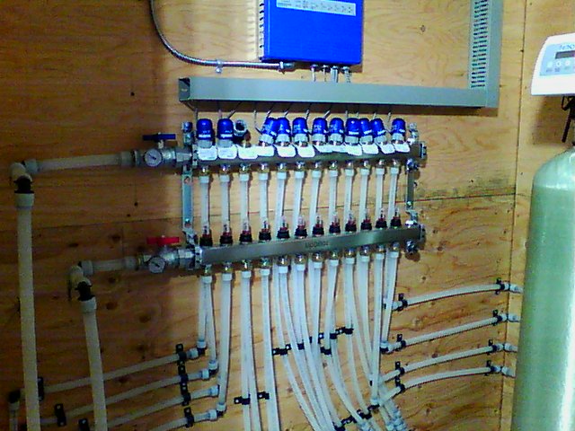
On the wall at the right are the manifolds and electric valves
for the upstairs underfloor heating zones. Above those are the driver electronics
to operate the valves.
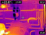
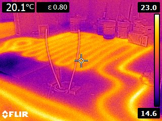
The same view in thermal infrared. The pump is in heating mode, so the ground
loop is dark (cold) while the inside loop is warm (yellow)
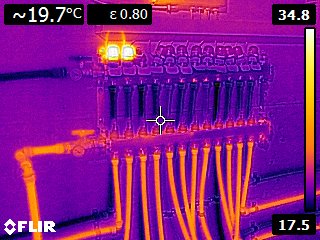
Manifolds and valves for the downstairs zones. The thermostats aren't
all connected yet, so all the electric valves are disconnected except two.
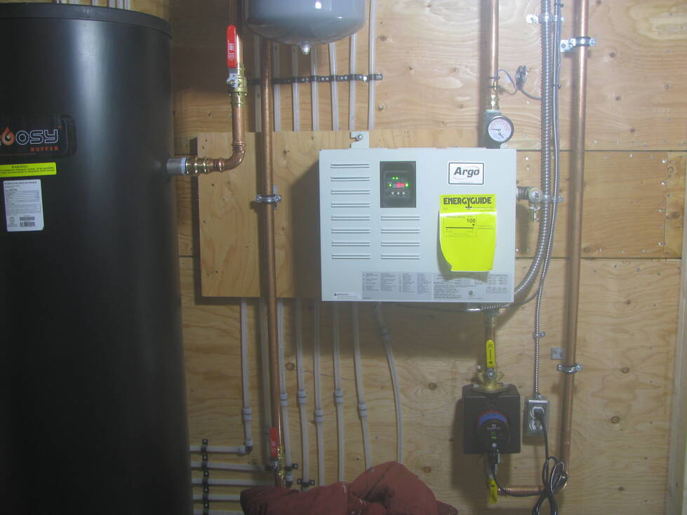
The auxiliary electric boiler. It seems to be unnecessary
even in cold weather (-6C).
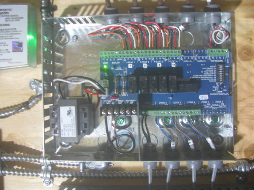
Inside one of the driver electronics modules. Wires at the top go
to room thermostats, wires at the bottom go to valve motors.
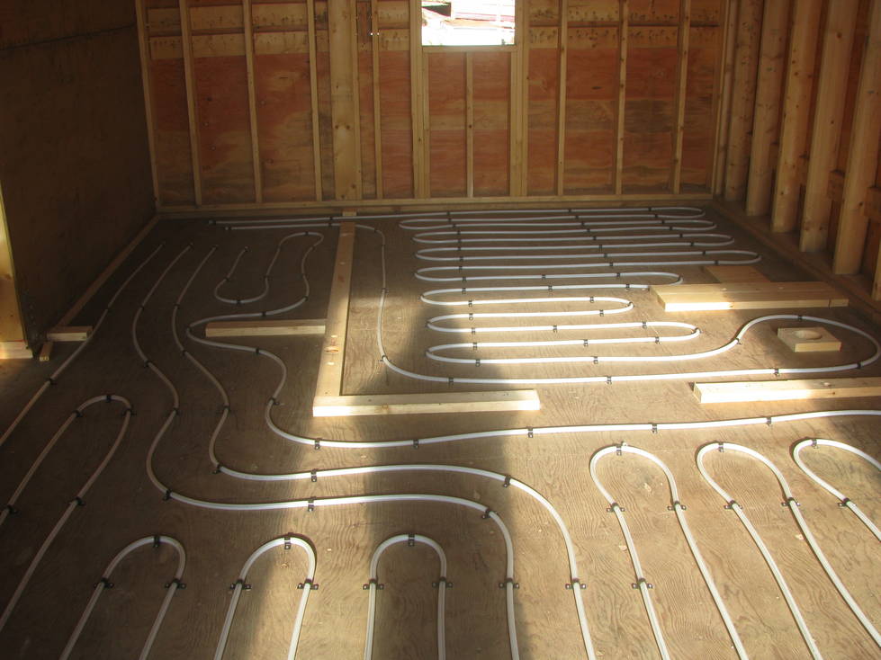
Underfloor heating loops on the main floor, prior to pouring
concrete.
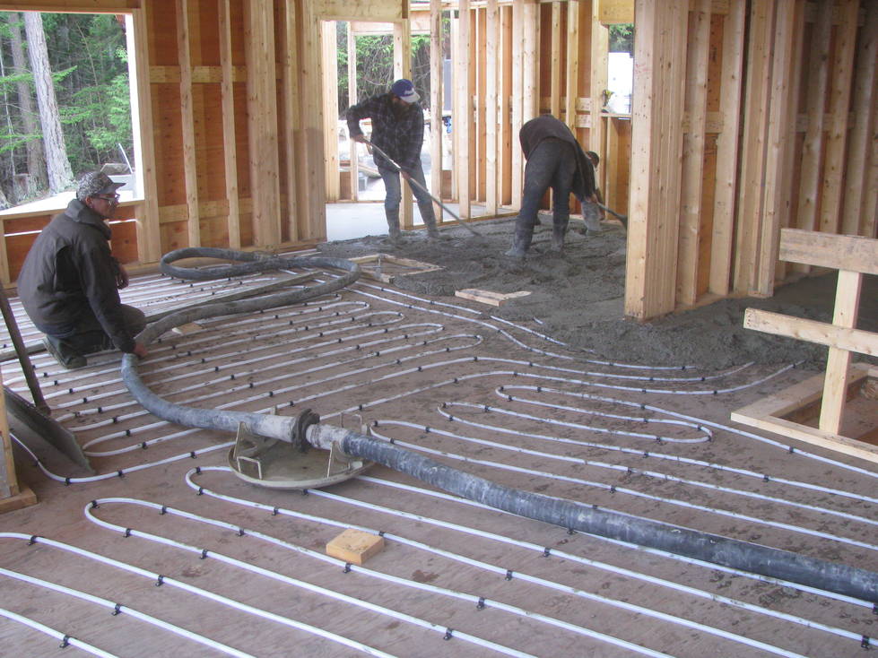
Pouring concrete on the main floor.
Underfloor heating loops in the kitchen; the gap is for an island (not
yet fitted).
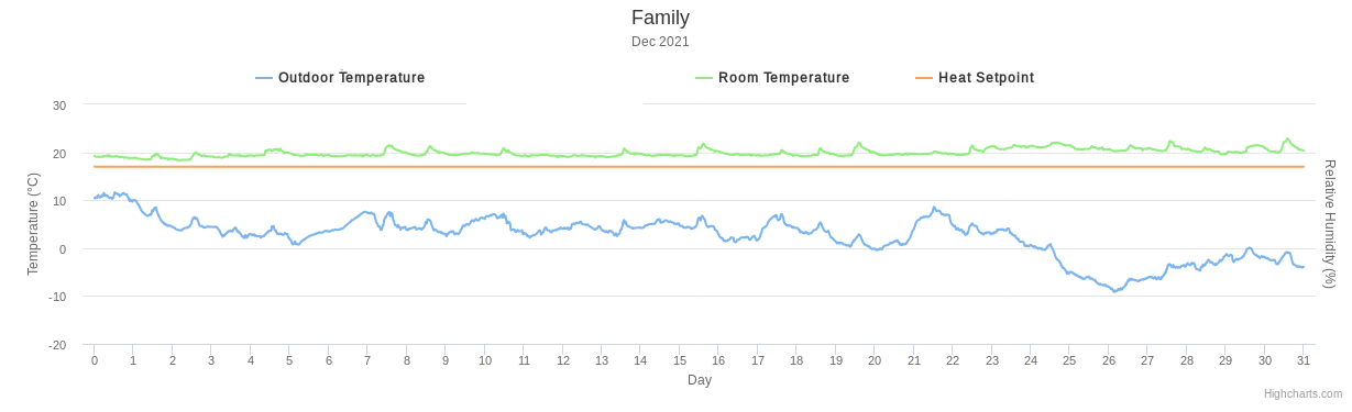
System in heating mode, December 2021
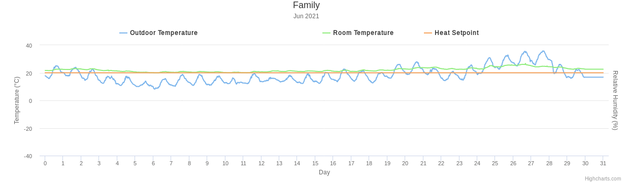
System in cooling mode, June 2021. I didn't actally switch to cooling mode till about June 24 when it got hot.